
CAN-Bridge · evaluation board · 12 V systems
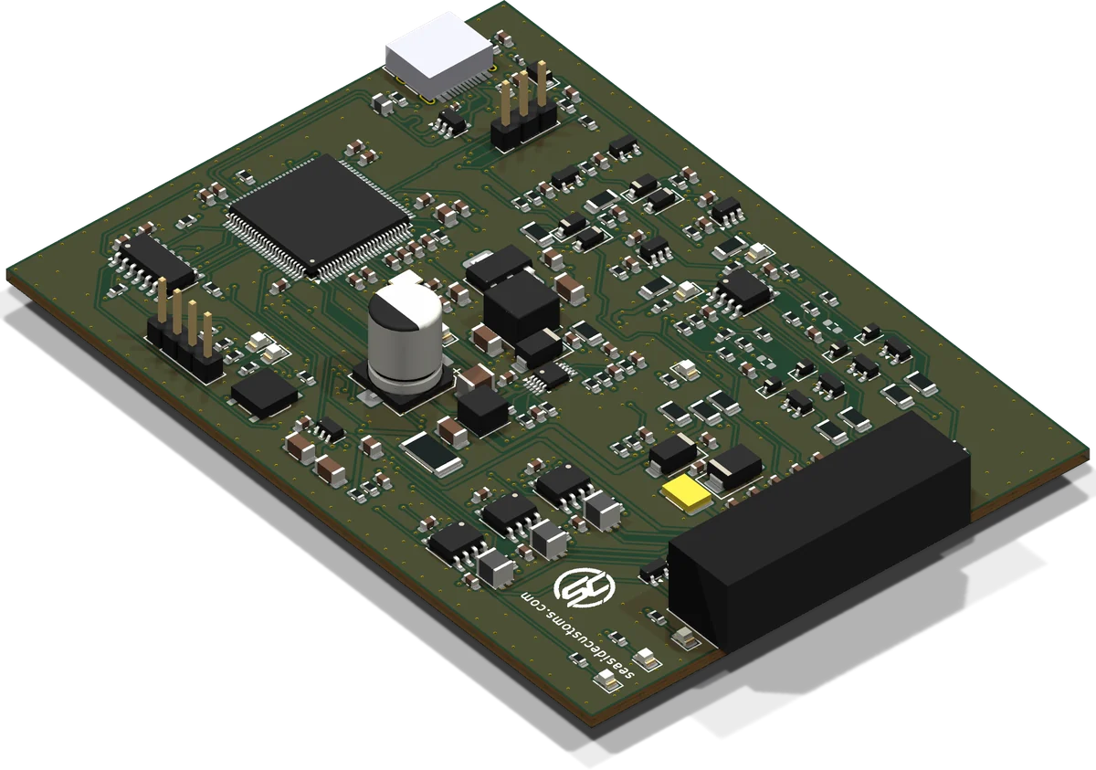
A CAN evaluation board with three independent CAN channels, analogue, frequency and switch inputs, and a 5 V supply output for sensors. The board has no fixed function: the loaded software decides what each CAN channel and each connector input does.
STM32F407 · 3× CAN incl. CAN FD · 12 V (6–16 V) · USB-C · for bench testing
Intended use
For professionals only: workshops, automotive electronics services, R&D departments and test bench builders. Operation requires knowledge of vehicle electrics and the CAN bus.
The product is not intended for consumers.
Description
The board is supplied as hardware and the user loads the software via USB-C. The software determines the speeds and roles of CAN1–CAN3, the meaning of the inputs (pressure, position, temperature or speed sensor, or a switch) and the meaning of the indicator LEDs.
Available Seaside Customs software: W212-Bridge (engine ↔ body communication, Mercedes W204 / W207 / W212) and VGS-Bridge (7G-Tronic gearbox on a test bench). The pin assignment is given in the documentation of the respective software.
Features
ARM Cortex-M4F, 168 MHz, 512 kB FLASH, 192 kB RAM. Software loading via USB-C or SWD, recovery mode with the BOOT button (USB DFU).
CAN1 and CAN2 up to 1 Mbit/s, CAN3 with CAN FD up to 5 Mbit/s (MCP2518FD). TJA1042 transceivers rated for ±58 V, filter and ESD protection on every channel.
3× analogue 0–5 V, 1× resistive (e.g. NTC), 2× differential frequency (VR sensors, square-wave signal), 2× switch to ground. Each protected against shorts up to 24 V.
Operates from approx. 6 V, polymer fuse, overvoltage and reverse-polarity protection. +5 V output for sensors. The logic can run from USB-C alone.
Molex Micro-Fit 3.0 2×10, USB-C with ESD protection, SWD and UART (3.3 V). 9 LEDs: power, status, error, CAN1–3 activity, FIN1/FIN2 inputs.
70 × 98 mm, 4 layers, solid ground planes. SMD components on the top side only.
Board view and connector
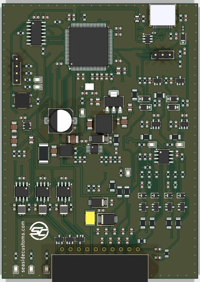
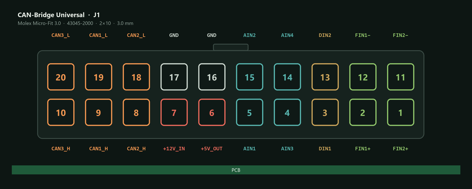
Pin names describe the circuit type, not the measured quantity. The role of each pin is defined by the loaded software. The board has no CAN termination — if the board is at the end of the bus, add a 120 Ω resistor in the test harness.
A full description of the connectors, LEDs, power path and dimensions is in the datasheet.
Datasheet (PDF)Specifications
| Hardware revision | C |
| Processor | STM32F407VET6 (ARM Cortex-M4F, 168 MHz) |
| CAN channels | 2× CAN 2.0A/B up to 1 Mbit/s, 1× CAN 2.0A/B / CAN FD up to 5 Mbit/s |
| Inputs | 3× analogue 0–5 V, 1× resistive, 2× frequency, 2× switch to ground |
| Sensor supply output | +5 V, max. 50 mA |
| Power | 12 V (6–16 V), logic also from USB-C |
| Quiescent current | approx. 47 mA at 12 V (max. 71 mA, calculated value) |
| Maximum current draw | 0.13 A at 12 V (calculated value) |
| Interfaces | USB-C (USB 2.0 Full-Speed), SWD, UART 3.3 V |
| Main connector | Molex Micro-Fit 3.0, 2×10 (cable plug 43025-2000) |
| Operating temperature | −40…+85 °C (design assumption) |
| PCB dimensions | 70 × 98 mm |
Tell us which ECUs you want to test on the bench — we will suggest the right software. garage@seasidecustoms.com
Compliance · disposal
CE marking: [TO BE CONFIRMED]
Scope of directives and standards: [TO BE CONFIRMED]
Class A equipment. In a residential environment this equipment may cause radio interference.
EU declaration of conformity: [TO BE COMPLETED]
The crossed-out wheeled bin symbol means that the used device must not be disposed of with household waste. Take it to a collection point for waste electrical and electronic equipment or return it to the manufacturer. Separate collection protects the environment and health from hazardous substances.
BDO registration number (PL): [TO BE COMPLETED]
Seaside Customs Garage products are test and development modules for professionals. They have no road approval and are not intended for permanent operation in a vehicle, for use while driving or on public roads. Changing CAN communication affects safety-critical systems: carry out tests and software updates only on a test bench or in an immobilised vehicle, and disconnect the module after the test. The user is responsible for how the product is used and for compliance with local regulations.